2 Months
2 hrs./day
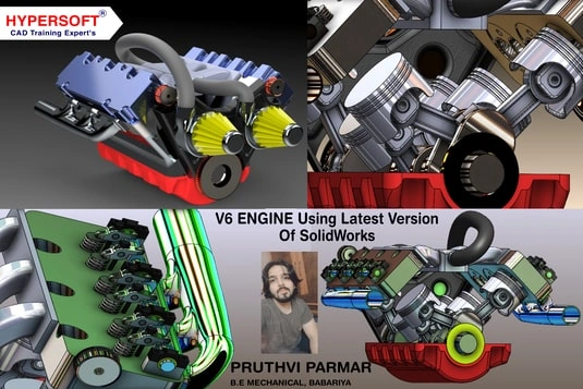
Creo Classes in Vadodara
Take Your Career to the Next Level with Best Creo Training Center in Vadodara
Our students work at well-known companies


About Creo Classes in Vadodara
1. What is Creo?
- Creo (formerly known as ProE) is a 3D CAD and CAE parametric software developed for designing and simulating mechanical products.
- Used for part modeling, assemblies, sheet metal, piping and cabling, mold design, weldments, and motion analysis across various industries.
- Includes essential FEA (Finite Element Analysis) and CFD (Computational Fluid Dynamics) tools for engineering simulation.
- Creo is a product of PTC (Parametric Technology Corporation), a global leader in product development software known for its robust, scalable, and innovative design solutions.
2. What is Difference between SolidWorks & Creo?
Purpose:
- SolidWorks: Focuses on 3D parametric modeling and simulation, mainly used for mechanical product design and engineering analysis.
- Creo: A comprehensive parametric CAD and CAE solution designed for advanced 3D product development, simulation, and manufacturing processes.
Industry Usage:
- SolidWorks: Primarily used in mechanical, aerospace, automotive, and manufacturing industries for product design.
- Creo: Widely used in high-end mechanical, aerospace, automotive, industrial equipment, and medical device industries for complex product development.
Functionality:
- SolidWorks: Specializes in 3D parametric design, assembly modeling, simulation, FEA, and rendering with a focus on mechanical components and systems.
- Creo: Offers advanced capabilities in parametric and direct modeling, topology optimization, generative design, simulation, additive manufacturing, and IoT integration.
Drafting & Designing:
- SolidWorks: Excels in 3D design, but also provides integrated tools for generating 2D drawings from 3D models for manufacturing documentation.
- Creo: Strong in both parametric 3D modeling and 2D drafting, with powerful tools for detailing, tolerance analysis, and model-based definition (MBD).
Conclusion:
Both SolidWorks and Creo are leading 3D CAD platforms tailored for mechanical design and simulation. SolidWorks is user-friendly and popular for mid-level product design, while Creo is preferred for complex, high-performance fluid engineering projects requiring deep simulation, customization, and enterprise-level scalability. The choice depends on project complexity, industry standards, and specific engineering needs.
3. What is Creo used for?
- 3D Machine Design:
Creating complex 3D models of mechanical parts and assemblies, making Creo ideal for precise and high-performance machine design. - Fluid Machinery Design:
Creo is widely used in industries that require precise design and simulation of fluid-related machines—such as pumps, valves, piping systems, and fluid power components—thanks to its robust CFD tools and parametric modeling flexibility. - Simulation and Analysis:
Performing advanced engineering simulations, including Finite Element Analysis (FEA) and Computational Fluid Dynamics (CFD), to assess structural integrity, thermal performance, and fluid behavior—especially valuable in the design of pumps, compressors, turbines, and other fluid-handling machinery. - Product Development:
Accelerating the design cycle with parametric and direct modeling tools, allowing for rapid modifications, design iterations, and optimization throughout the product development process. - Technical Documentation:
Automatically generating accurate 2D drawings and manufacturing documentation from 3D models, ensuring consistency and clarity in production and assembly.
4. What are the benefits of learning Creo?
- High Demand for Jobs:
There is a strong and growing demand for professionals skilled in Creo, especially in advanced mechanical design, simulation, and manufacturing sectors. This translates into more job opportunities for you in high-tech industries. - Better Salary Potential:
Creo expertise is highly valued, and companies often offer better salary packages to professionals who can efficiently design, simulate, and optimize complex engineering products. - Career Growth Opportunities:
With Creo skills, you can move into specialized engineering roles, R&D positions, or even leadership tracks in product development and design teams. - Enhanced Design Skills:
Mastering Creo enables you to handle complex assemblies, perform simulations (FEA/CFD), and optimize designs, making you a more capable and competitive engineer. - Versatility in Roles:
Creo is used across aerospace, automotive, industrial equipment, medical devices, and fluid machinery design. Your skills will be applicable in a wide range of industries, giving you greater career flexibility.
5. What opportunities are available after learning Creo?
- High Demand for Jobs:
There is a strong and growing demand for professionals trained in Creo, especially in mechanical design and product development. Enrolling in Creo classes in Vadodara gives you a competitive edge in local and global job markets. - Better Salary Potential:
Companies are actively seeking Creo professionals, and many offer higher salary packages to those skilled in 3D modeling and simulation. By taking professional Creo training in Vadodara, you increase your chances of landing well-paying roles in top engineering firms. - Career Growth Opportunities:
Learning from industry experts through Creo certification courses in Vadodara can help you move into specialized or leadership positions in design and engineering teams. - Enhanced Design Skills:
Through hands-on learning in advanced Creo courses in Vadodara, you’ll master the tools needed to build complex 3D models, simulate performance, and solve real-world engineering problems. - Versatility in Roles:
Creo is widely used in industries such as automotive, aerospace, fluid machinery, and industrial equipment design. Completing a Creo training program in Vadodara prepares you for multiple career paths, both in India and abroad.
6. Who can learn Creo course?
- Engineering Students:
Students pursuing ITI, diploma, or degree programs in mechanical, electrical, automobile, or aeronautical engineering can greatly benefit from learning Creo. It’s a valuable skill that enhances their design capabilities and job prospects. - Industry Professionals:
Production engineers, quality engineers, and technical sales professionals looking to shift into design roles or move up in their careers can use Creo to expand their skill set and take on more technical responsibilities. - Manufacturing Engineers:
Those working in manufacturing roles can improve their understanding of product design, development processes, and digital prototyping by learning Creo. - Entrepreneurs & Startups:
Entrepreneurs involved in product-based businesses can use Creo to develop accurate, professional-grade designs, streamlining their development and manufacturing workflows. - Aspiring Product Designers:
If you’re interested in product development or pursuing a career in design and engineering, Creo provides the tools you need to bring your ideas to life.
Taking Creo classes in Vadodara can be the perfect first step toward building that skill set.
This course includes:
- From Zero to Advance Level training
- Courses Content Crafted by industry experts.
- Theory & Practice Book
- Personalized Doubts Solving
- Government approved International certification
- Post Training Support
- Placement Assistance
What You’ll Learn in Creo Training at Hypersoft
1. Creo Interface & 2D Sketch
- Sketching Tools
Use sketching tools like Line, Rectangle (Corner, Slanted, Center, Parallelogram), Circle, Arc, Ellipse, Delete and Spline to create simple and complex shapes for your design. - Fillet and Chamfer
Use Fillet to round edges and Chamfer for angled edges, allowing for smooth transitions and improving the flow of the design, especially in wire harness components. - Trim Tools
Use Circular Trim and Elliptical Trim to remove unwanted portions of your sketches, refining your design by ensuring only the necessary elements remain. - Constraints and Symmetry
Maintain design accuracy with Constrain Box tools such as Vertical, Horizontal, Perpendicular, Tangent, Coincident, Symmetric, Parallel, and Equal. These help control relationships between sketch elements and ensure proper alignment. - Coordinate System & Reference Geometry
Establish a Coordinate System for precise positioning and use Reference Geometry to create datum planes, axes, and points, offering a solid foundation for 3D modeling. - Offset, Mirror, and Thicken Tools
The Offset tool creates parallel lines at a fixed distance from an existing element, while the Mirror tool duplicates sketch entities symmetrically. Use the Thicken tool to add thickness to surfaces or features in the design, helping to create the desired geometry for wire harness components. - Rotate and Resize
Use the Rotate Resize tool to adjust the orientation or scale of your sketch elements, helping you fine-tune the layout for wire harnessing and component fitting. - Text, Point, and Corner Tools
Add Text for annotations, use Point for marking specific locations, and apply Corner for rounding the intersections of sketch elements. These tools ensure clarity and organization in your wire harness design.
2. Part Design
- Part Creation Tools (Extrude, Revolve):
Use Extrude and Revolve to convert 2D sketches into 3D models. These core tools are essential for creating solid shapes and forms for any mechanical design. - Datum Plane and Shell:
Define reference geometry with Datum Planes, crucial for positioning and constructing features. Use the Shell tool to hollow out parts and optimize material usage. - Mirror, Round, and Chamfer:
Duplicate features symmetrically using Mirror. Use Round to smooth edges for better design flow and Chamfer to apply beveled edges for aesthetics and functionality. - Hole and Sweep Tools:
Create precise holes for fasteners or fittings using the Hole tool. With Sweep, generate curved or complex shapes by sweeping a profile along a path. - Axis and Point Creation:
Establish reference geometry with Axis and Point tools. These are vital for defining rotation, symmetry, or precise feature placement in part design.
3. Advance Part Design
- Swept Blend and Pattern Tools:
Use Swept Blend to create complex transitions along multiple paths. The Pattern tool helps replicate features with control over direction, axis, curves, and reference points. - Data Management (Get Data Import & Tree Filter):
Bring in external files with Get Data Import for smoother project integration. Use the Tree Filter to manage and navigate large, complex models more efficiently. - Annotation, Reference, and Parameters:
Add dimensions and design notes with Annotate. Use the Reference Viewer to track model dependencies. Parameters allow dynamic control of features, enabling easy updates and adjustments. - Shrink Wrap and Investigation Tools:
Simplify your models with Shrink Wrap to create lightweight versions for sharing or collaboration. Use Investigation Tools to analyze design integrity and performance. - Display & View Tools:
Enhance design clarity using Display Style, Repaint, and Orientation View Save. The View Manager lets you control visibility, while Datum Display Filter manages reference elements. Pallets give quick access to commonly used tools for a more efficient workflow.
4. Entry-Level Sheet Metal Part Modeling
- Walls in Sheet Metal:
Extrude: Create walls by extruding a 2D profile in sheet metal.
Revolve: Create a wall by revolving a profile around an axis.
Boundary Blend: Use boundary blending to form smooth transitions between different walls.
Attached Walls: Define walls that are attached to other existing components or walls.
- Sheet Metal Wall Types:
Flat: Create flat walls or surfaces in sheet metal designs.
Flange: Add flanged edges to walls for better attachment or bending.
Extend: Extend the length of existing walls or surfaces.
Twist: Apply twisting motion to walls for forming complex sheet metal shapes.
- Converting Part into Sheet Metal:
Use the Convert Part into Sheet Metal tool to convert a regular part into a sheet metal part, enabling the use of specific sheet metal tools. - Corner Relief:
Apply Corner Relief to avoid sharp angles in corners, which can make the sheet metal part difficult to manufacture. - Edge Bend:
Use the Edge Bend tool to create bends on the edges of the sheet metal part for further shaping and flexibility.
5. Assembly
- Adding Components to Assembly:
Use the Add Component tool to bring individual parts into the assembly. This allows you to place parts in the design space and begin the assembly process. - Applying Constraints:
To define relationships between components, apply various Constraints such as:
Default: The basic constraint to attach parts.
Coincident: Aligns two faces or edges to be coincident (in the same plane).
Distance: Sets a specific distance between two components.
Parallel: Ensures two parts or faces are parallel to each other.
Normal: Aligns parts at a perpendicular angle.
- Creating Sub-Assemblies:
Use Create Sub-Assembly to group components into smaller, manageable units within the main assembly. This helps in organizing the design and improves workflow by treating subassemblies as single components.
6. Advance Assembly Tools
- Replace Component
Swap out a part with another, while preserving constraints and references where possible. - Pattern Component
Repeat a component in a defined pattern (linear, circular, or by reference). - Flexible Components
Allow a part (like a spring or cable) to adapt its shape or position based on the assembly context. - Mirror Component
Insert a mirrored version of an existing part, useful for symmetrical assemblies. - Assembly Features
Create features (like cuts or holes) that affect multiple components directly within the assembly. - Exploded Views
Create exploded representations of the assembly for documentation or presentation. - Interference Check / Collision Detection (not analysis, but functional)
Automatically check if components interfere with each other during placement or motion.
7. Creating Drawing Views
- View Creation
Create general views, isometric views, partial views, and custom scale views to represent the model clearly. - Detail & Broken Views
Use detail views to zoom into complex areas and broken views to shorten elongated components while maintaining scale. - Cross-Section Views
Add cross-section views to show internal features and improve clarity in harness and assembly drawings. - Annotation & Symbol Creation
Apply dimensions, notes, balloons, and create custom symbols (e.g., for connectors or standard parts). - Table Management & Drawing Layout
Generate and manage BOMs, wire lists, revision tables, and prepare the drawing format and layout according to standards.
CREO Professional Course Completion - 2 Months
- Creo Trainer feedback on your your work throughout the course.
- Submission of a 3D Project created in Creo
- Professional Creo online exam (50% passing score required).
- Creo certification 🎓
How to Join Hypersoft Creo Classes


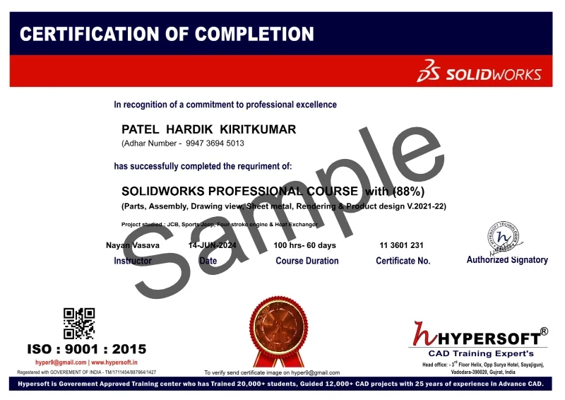
Creo Certifications
In today’s competitive job and college placement landscape, highlighting practical skills on your resume is important. Hypersoft’s industry-validated Creo course certifications, certified by NSDC, have the power to transform your resume. These certifications validate not only your Creo software skills but also your deep knowledge of the Designing, enhancing your credentials significantly.
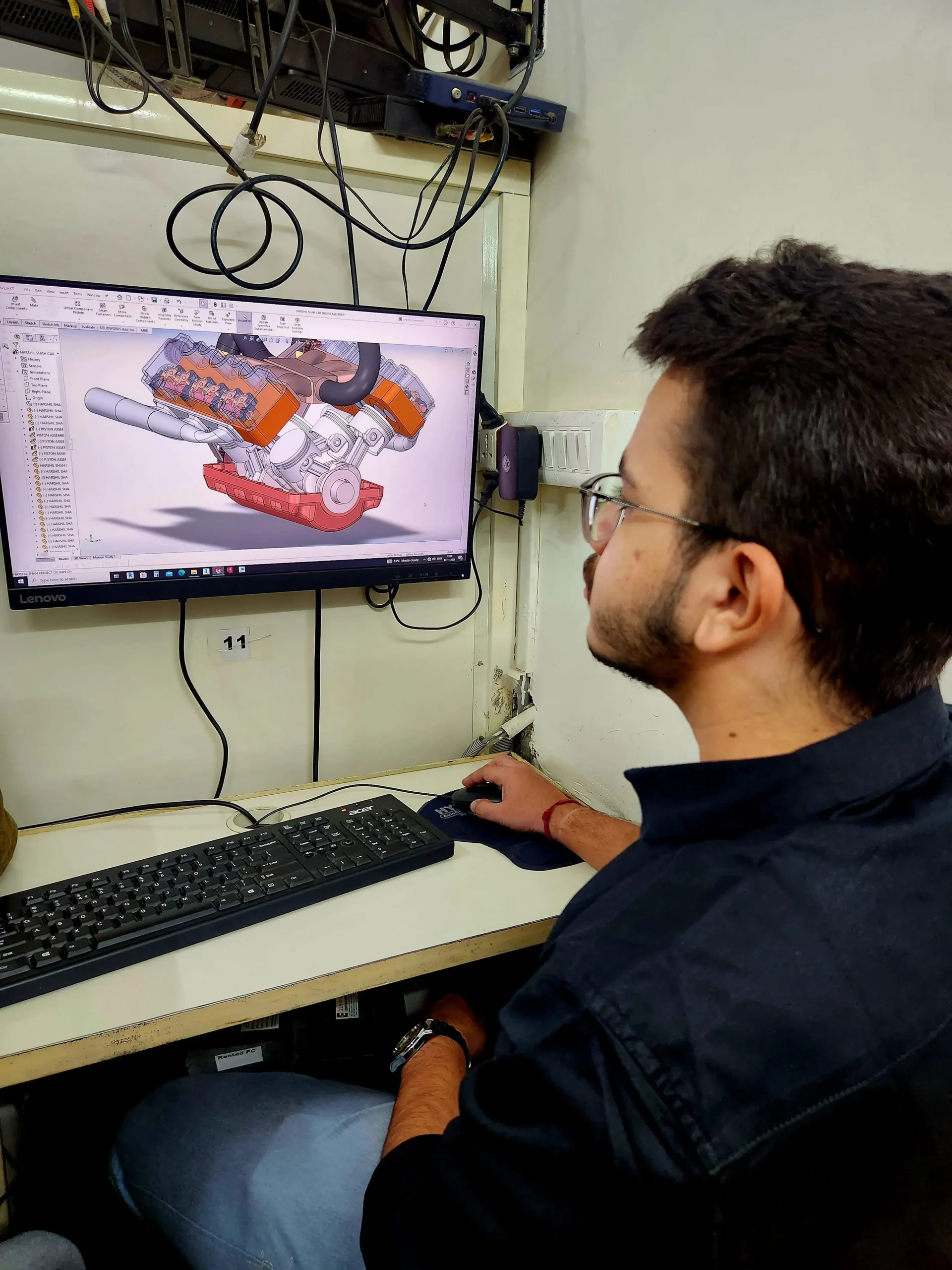
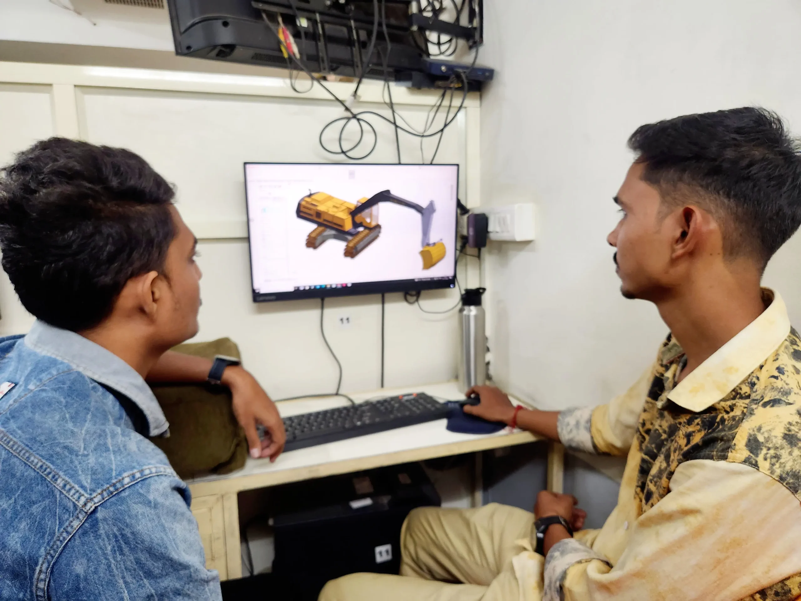
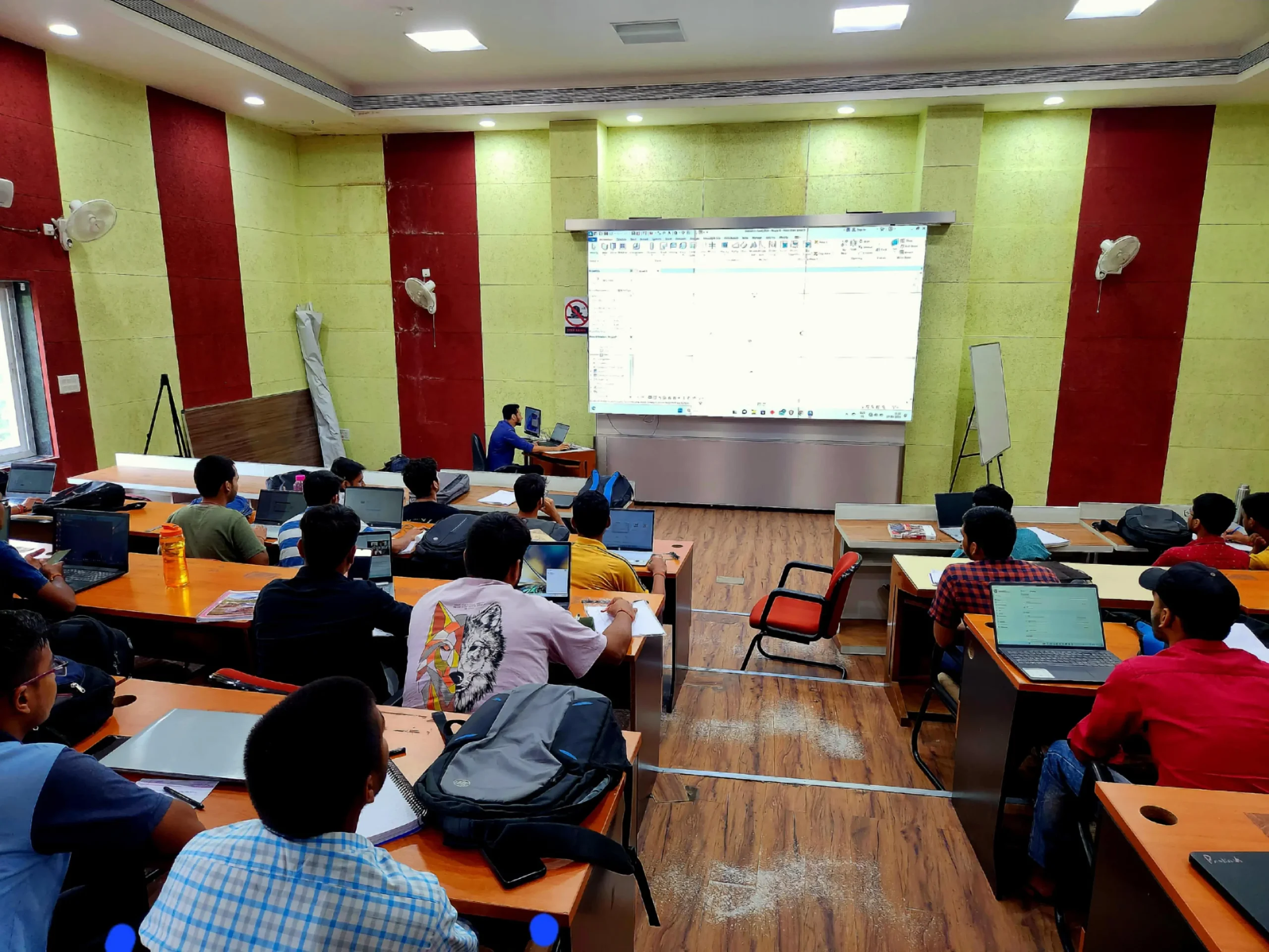
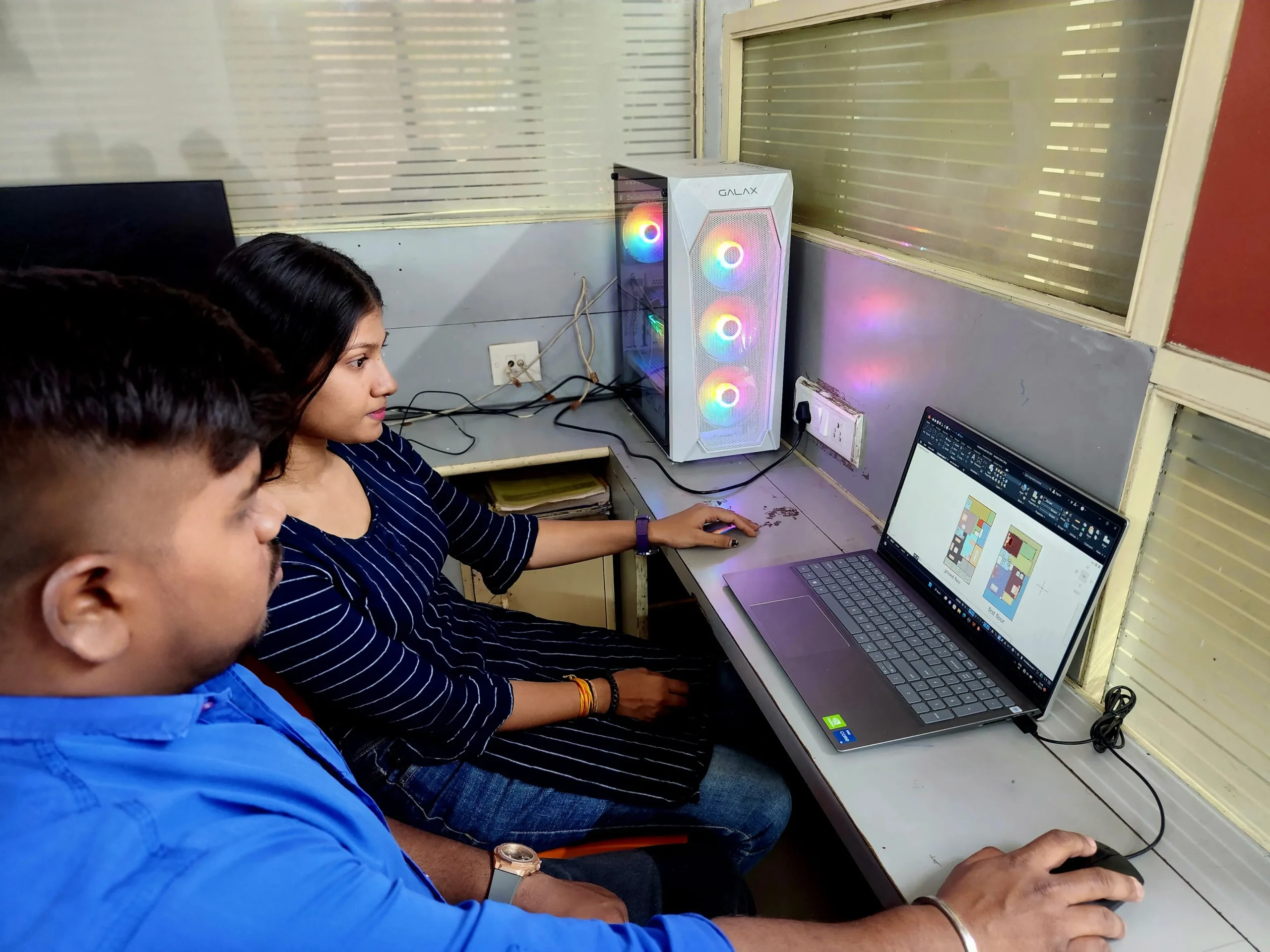
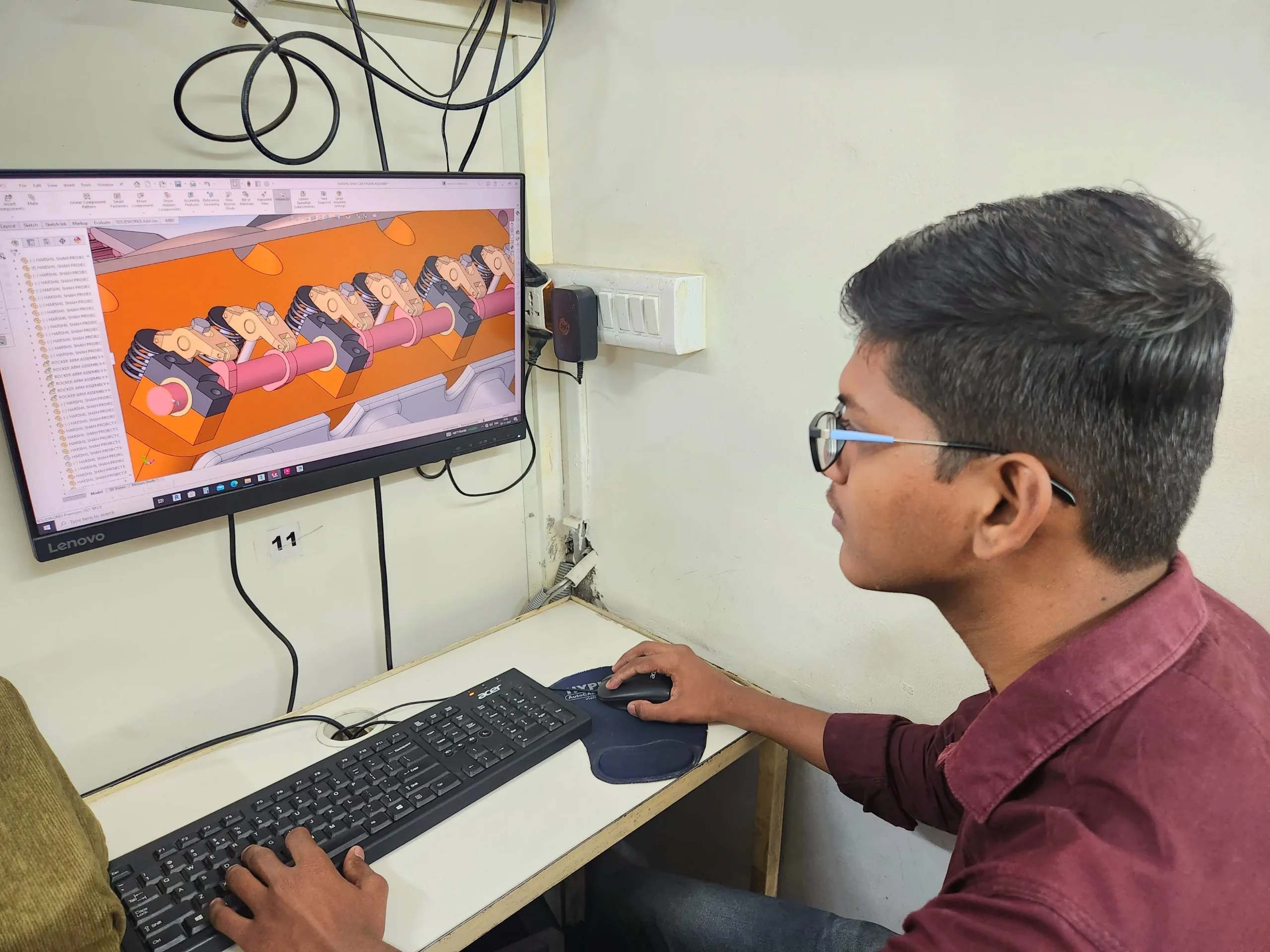
Hypersoft Sneak Peak
Sharing vibrant learning environment of our institute through photos of students’ learning experiences and trainers facilitating sessions.
Your Success, our goal
With extensive company partnerships, detailed training, and high student satisfaction, your future is in good hands.


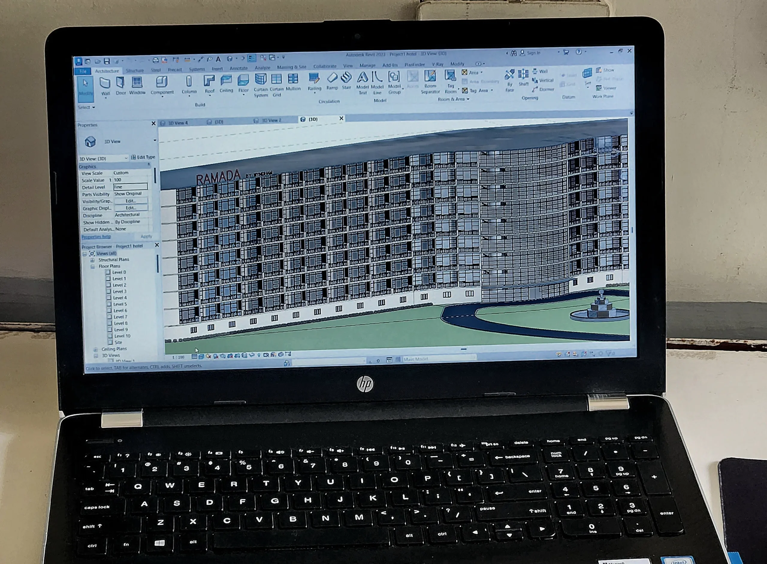
Creo Classes Students projects
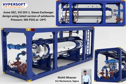
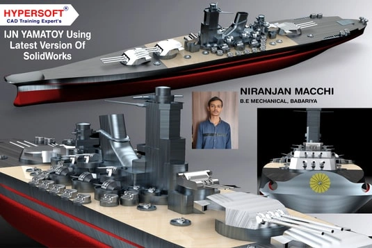
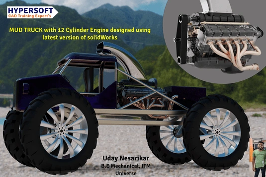
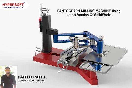
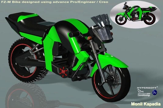
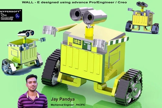
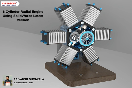
Hypersoft Leaners Succeed with Great Projects & Great Stories.
Explore Other Engineering Design Courses

SolidWorks Courses
📅 2 to 4 Months
🕑 2 hrs / Day
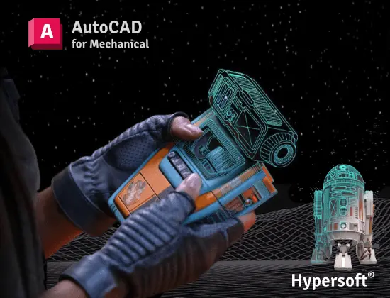
AutoCAD Course
📅 1.5 Months
🕑 1.5 hrs / Day
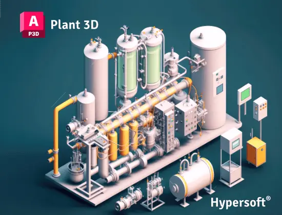
Plant 3D Courses
📅 1.5 Months
🕑 2 hrs / Day
Creo Course Help Desk & Student Support
What are the Creo class timings & Duration for this course?
PTC CREO batches start every 15 days:
- 1st Week of each month
- 3rd week of each month
Creo Professional Course
- Duration: 2 Months 📅
- Hours per Day: 2 hrs.🕑
Note:-
- Timings available from morning to evening ⏰ (Sunday OFF) ✨.
- If you want to complete the course faster ⏩, you can allocate more time per day.
- We also have a special batch for shift-duty employees 🏭.
To know about the new Creo batch call us at 📞 94278 99997 !
What are the course fees for Creo training?
Creo Professional Course Fees:- 12950/-
Note: Above fees are Laptop fees. If you don’t have laptop, then the fees will be Rs 13950/-
Laptop Fee: Students who bring their own laptops & use them at the center for practice laptop fees will be considered.
Premiums Fees: Students Using Hypersoft Workstation (Computer) for Practice
Creo classes are online or offline?
Is the Creo course being a certified course?
Yes🎉
You will be awarded an Creo international government-approved certification 🏅.
Certification requirements:
- Pass an online exam with a score of at least 50% 📝.
- Submit a project that demonstrates your skills 💻🔧.
Are there any Emi Options Available?
Yes❗
You can pay your Creo Professional fees in two installments.💼
Modes of Payment Accepted:
- Cash 💵
- UPI 📲
- Cheque 💰
- NEFT or IMPS 💻
Do you offer free demo classes for Creo?
We offer 2 free demo classes for AutoCAD, where you can:
- Experience our teaching approach 👨🏫
- Check Your Interest: Are You Ready to Start Your Design Journey? 💡
What are the laptop specifications required to run Creo software?
To efficiently run Creo 8 or later versions, the minimum system requirements are:
- CPU: Intel Core i5 10th Gen or AMD Ryzen 5 5th Gen (or above)
- RAM: 16 GB
- Storage: 256 GB NVMe or SSD
These specifications are the bare minimum required to operate the software effectively.
If you are planning to buy a new System, please refer:
Laptop Buying Guide for Engineering Designing.
From where can I download Creo software?
To download the software, please follow these steps:
1. Click here 🔗.
2. Register yourself add all details asked 📝.
3. Once confirmed, you’ll be able to download the software 💻.
You’re all set! 🎉
Note:- Students version file will not open in license Creo
Where can I download Creo exercises?
You can download SolidWorks practice exercises for:
- Part
- Assembly
- Sheetmetal
Your trainer will provide the file password 🔑.
Websites from where you can download free SolidWorks Models.
Will I get a job after completing the Creo course at Hypersoft?
Yes! Hypersoft provides comprehensive job placement support through JobKart, our dedicated placement portal 💼.
With over 25 years of industry connections 🤝, we regularly receive job openings from top companies.
After you join, you’ll be added to the Hypersoft Placement Group 👥 for direct job updates and career assistance.
With our strong network and placement services, you’ll be well-prepared to land a job after completing your training 🚀.
Which websites should I avoid for Creo downloads?
Warning: Avoid downloading Creo from unauthorized websites like
- FileCR,
- GetIntoPC, and
- unverified Telegram sources.
These platforms often distribute counterfeit or harmful software that can put your device at risk. Always download PTC from trusted sources, such as the official PTC Creo, to ensure the software is safe and legitimate.
How much do Creo classes cost?
Creo Offline or Online Training Costs: Typically range from Rs. 12,000 to Rs. 60,000 💸.
Key Factors to Consider Before Choosing a Training Institute:
- Reputation & Experience: Check how long the institute has been around and its expertise in SolidWorks.
- Learning Resources: Check if the course includes eBook, textbooks or any other material.
- Practice Exercises: Crucial for understanding the depth of knowledge you’ll gain and your readiness for real-world applications.
- Certification: Aim for certifications above ISO standards (ISO is a company standard, not meant for training certificates).
- Post-Training Support: Look for ongoing assistance after course completion.
- Job Placement Assistance: See if the institute offers career support or placement services after the course.
- Alumni Feedback: Look for reviews or testimonials from previous students to gauge the quality of the training.
Hypersoft meets all 7 key factors mentioned above while keeping fees affordable and accessible.
What happens if I don't attend classes regularly?
If you miss more than 5 classes without written leave, your admission may be suspended.
You’ll be required to pay a re-activation fee of Rs. 500 or more.
Additionally, you won’t be able to attend makeup classes for the missed lectures 📚, and you may not be eligible to apply to top companies through Hypersoft Placement 💼.
Stay Regular & take written leave from trainer to gain maximum benefit of your learning journey! ✅
I was not able to attend a session. Will i get a refund for it?
Our refund window is open for 5 days from the date of admission.
However, for your convenience, you can reschedule your enrollment to another batch with a minimal transfer fee. 😊🔄
Will I get a job after completing the Creo course at Hypersoft?
Yes🙌
Hypersoft provides comprehensive job placement support through JobKart, our dedicated placement portal 💼.
With over 25 years of industry connections 🤝, we regularly receive job openings from top companies.
After you join, you’ll be added to the Hypersoft Placement Group 👥 for direct job updates and career assistance.
With our strong network and placement services, you’ll be well-prepared to land a job after completing your training 🚀.
What are the benefits of learning Creo in Vadodara?
- Enhanced employability with a skill highly sought after in industries like engineering, and manufacturing 🏗️🏭.
- Entry into white-collar job sectors where AutoCAD expertise is often a prerequisite for roles in design, engineering, and project management 💼🛠️.
- Career growth and higher salary potential in companies that value AutoCAD proficiency 📈💰.
What if I leave the class and want to complete it later or require a certificate?
If you take a break of more than 15 days without written leave.
A reactivation fee of ₹2,500 will be required ⚠️.
if you missed your exam you’ll need to pay an exam fee of ₹2,000 📜💰To get a certificate later.
Exams are conducted within 10-12 days after the course duration, or earlier if required.
How can I find Best Creo classes in Vadodara?
- Google “Creo classes in Vadodara” 🌐, read reviews ⭐, and visit the top-rated institutes. Hypersoft is the top-rated institute in Vadodara with 25+ years of expertise 🏅.
- Check the brand value of the institute 🔍. Institutes with a strong brand value tend to have better credibility and higher placement rates 📈.
- Also, ask friends 👥, seniors 🎓, or faculty 👨🏫 for recommendations.
What happens if I am unable to complete the course within given time?
If you are unable to complete the course within the given duration, don’t worry—we offer an extended time of 1.5 times the original duration to complete the course. 🕒
For example, if your course duration is 60 days, you can complete it in 90 days. 🗓️
After receiving your certification, you’ll become a valued member of the Hypersoft alumni network & you will get
- doubt resolution +
- revision assistance +
- access to premium masterclasses +
- placement 🎓😃🎉
All free of charge for a lifetime! 😲